Ad blocker detected: Our website is made possible by displaying online advertisements to our visitors. Please consider supporting us by disabling your ad blocker on our website.
Yes it is 1/12 scale must say its an absolute dream even for myself with little experience in modeling it goes together quite well. Thanks for all the advice guys.
small bit of progress today, got a few parts painted in x-18 (semi gloss black) need to do some more painting in xf-1 (flat black) next before i can assemble any further. the front end suspension wise is all glued together now into the monocoque no pictures as of yet because its all covered in masking tape to ensure it glues to all the bits it is suppose too. one picture i will leave you with is the finished oil pump with homemade a/n fittings and 1.5mm braided hose
Just a small update, I have finished off most of the engine. I just need to add springs back onto the exhaust system and finish off the oil cooling plumbing to the rear of the gearbox.
the Top half of the monocoque has been a complete mess. my third and hopefully final replacement has arrived from Japan and I will attempt to have this painted within the coming weeks, providing all goes well I should have a top half I can finally glue down and make some headway with this project, this really is the only part holding me up at the moment.
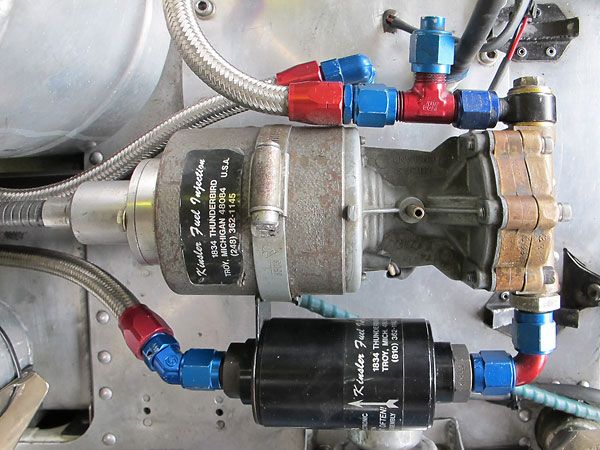
I"m no expert either. As Terry says. But that is the mechanical fuel pump on top with the black unit a fuel filter. The picture is from Phil Mauger"s McLaren M23 ex Denny Hulme 1973 M23. See WWW.BritishRaceCar.com for great detail pictures of this M23.This will really help you with this nice build you are doing.
Thanks for that, i do have all of those pictures saved in my reference folder along with the Hiro Pictoral some of the wires are really hard to trace as they seem to dissappear into darkness. i will add what i can but it will never be 100% accurate it is my first build after all
Very nice work on this Mclaren M23. In my build I also used Plastruct hex to make my own A/N-fittings. You did an excallent job to make them. Keep up the good work.
adamg1987 wrote:
can anyone tell me where the two braided hoses on his picture to the left lead too?
I'm no Cosworth expert (Stephen is the man for that) but this engine appears to be running a much later fuel system (restored car and hence why I assume) because it has an electric pump with a mechanical drive. The two braided hoses to the left are from top to bottom; the main fuel return and the fuel to the metering unit. Hope that helps.
Hi
Sorry I didn't get into following this thread before. Terry is correct, the system in these pics is not period correct for this car as it was developed several years after this car raced. For all the details, may I suggest "Plumbing & Wiring Strategies for the DFV". It answers all the questions about stuff that disappears into shadows. While other references can be helpful, "Plumbing & Wiring Strategies for the DFV" still continues to offer the most comprehensive clarity to detailing the DFV. http://members.shaw.ca/millersbrm/publications2.html