Here we go again. Did some research for the right colour of the chassis. I found different varyities on different models. In the end I found also some pictures of the 1:1 car.
It's in the Ferrari museum. Also nice to see some details, useful on the build.


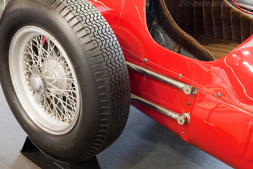
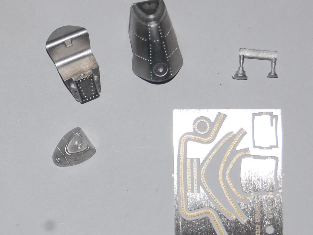
One can see also that the inside of the body parts remain unpainted. I will do the same for my model.
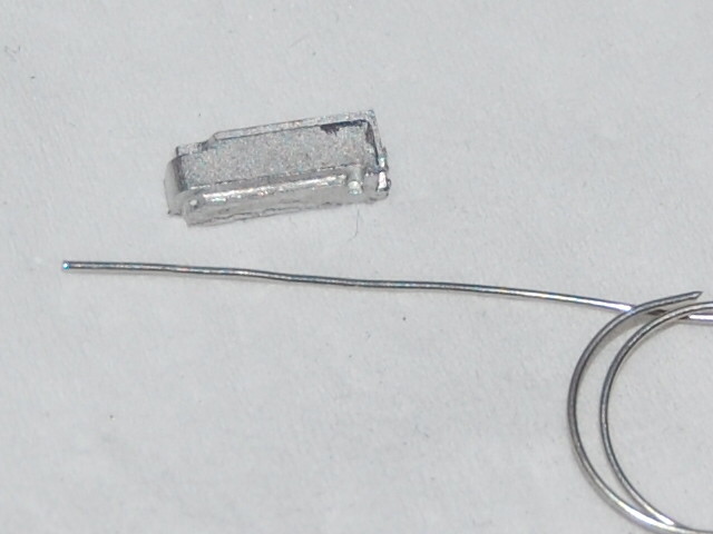
Here one of the body parts as an example. Very delicate, and easy to bend in wrong ways.


Now on with some tricky bending works. Tameo provided some special templates for this.
The theory:


And for real, step by step:

The templates are realy smart designed. They have a front and a back side. By the different width of the slots you can't go wrong.

And then you press all together.

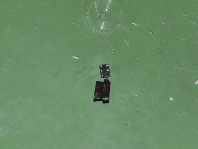
The result. It was very hard to get the formed metal out of the template without damage.

The left side is different, so another template.

You have to bend a 0,5 mm edge.

Then you have to glue the top side on. Very small to handle as you can see. (I have normal size fingers).

I glued these parts in the fire wall when still in the sprue to prevent flexing and bending.
CA glue residu will beremved with acetone later.

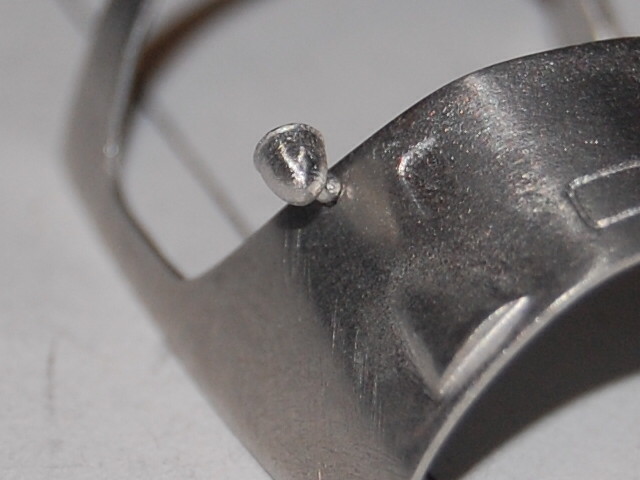
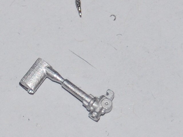
The FE throttle pedal. Again some complex and tiny bending to do.

You have to use a 1mm x 0,4 mm rod to assemble the pedal.

The little hole is for the rod which will connect the pedal with the carburators on the engine.
Assembled in the fire wall. Some polishing to do later. Later a break pedal will be added, connected with break cilinders.
But firts some rest for my old eyes.

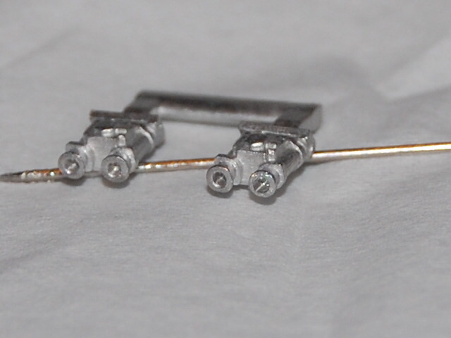
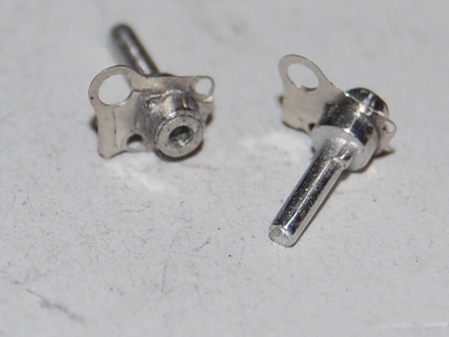
The break pedal provided with a 1,2 mm rod, placed from the under side in the break cilinder.

And assembled. Here to be seen from the engine side.

After the cilinder in place. The pedal itself must be added.

Worked with acid to get the right colour and wear.
The driver side with the break and throtte pedal.

Further with working on the body parts. More work than initially thought. Flash and burrs?


One of the side panels. Drilled and the FE part assembled.

Then disaster struck. Bend in the procces of sanding.

Twisted in different direction. Because the metal is so thin, I get onlu a few attempts to correct this before the parts shears off.
Because I don't want to manipulate this part too much, I decided to first place the mirrors, as the will be sprayed also in the body colour.
Filing the inner pins flush with the inside of the body panel. Again danger for too much bending.

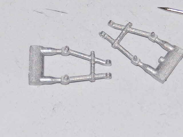
I decided to glue one of the chassis arches on a credit card to create a sort of template without bending the arch.
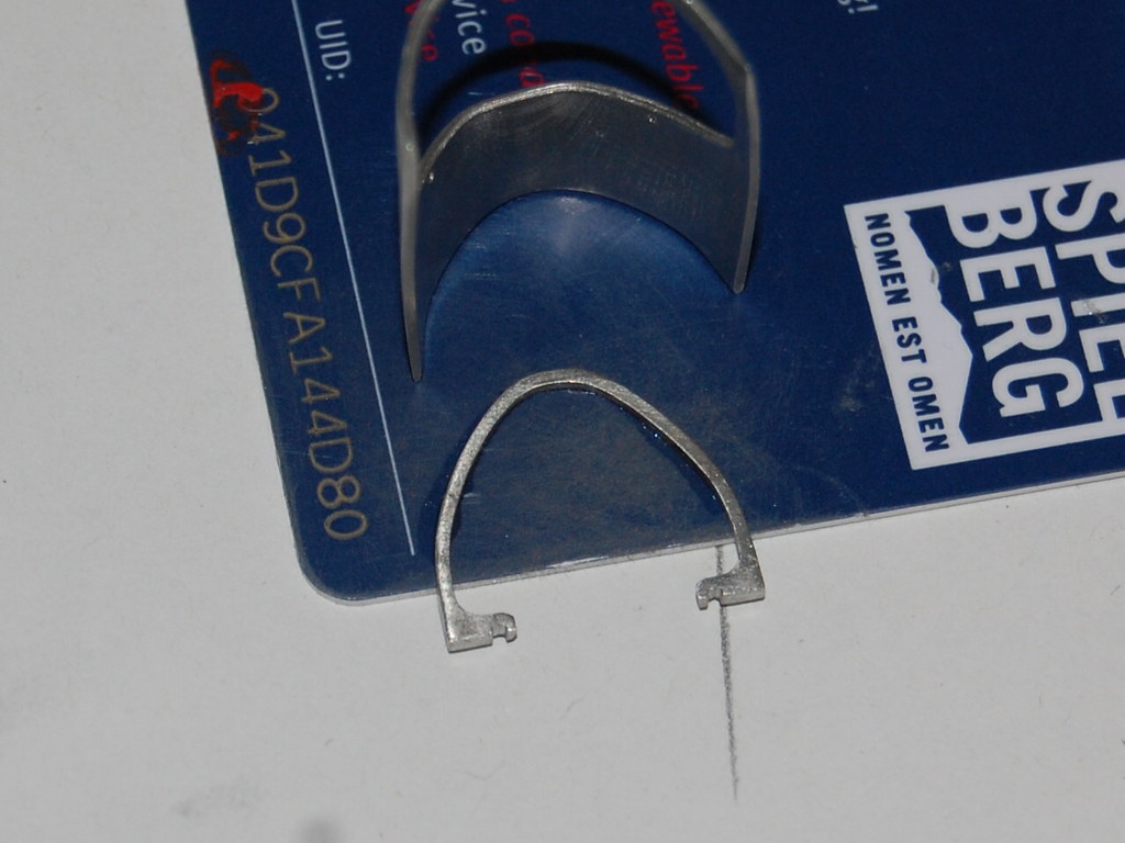
The amount of bending needed.

The end result. I managed to save the body part.

The arch rescued. The CC plastic desolved in the acetone, as did the AC glue.

To prevent unauthorized bending, the arch glued on the chassis.

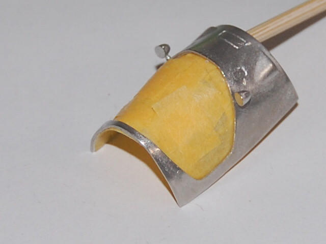
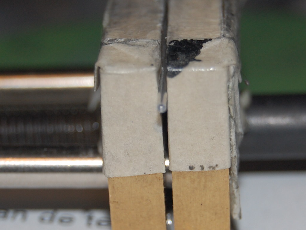
Starting to mask the body parts. A time consuming task. Done to keep the inside of the body parts aluminium colour. I attach sticks so I can handle the parts during aurbrushing.

Time for some bending of lots of FE parts.


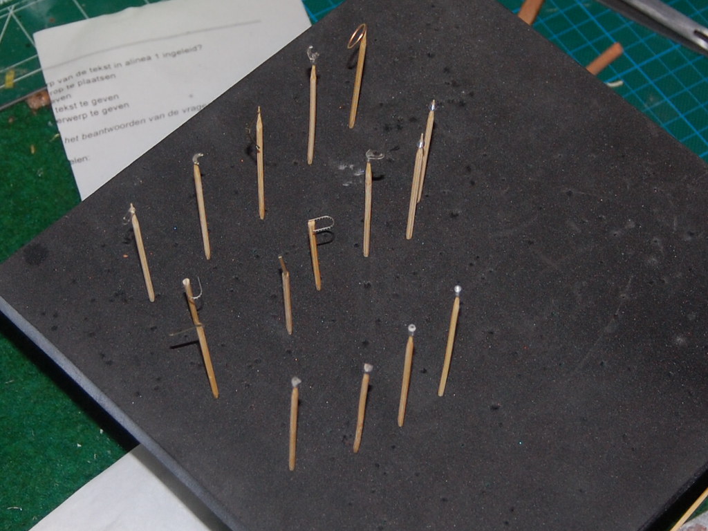
And some really tiny parts on sticks for spraying later.

I already glue the fins on the side panel. To get a smooth finish later.


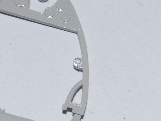
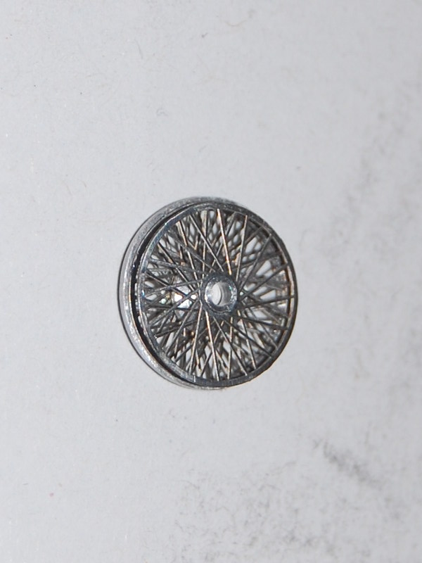
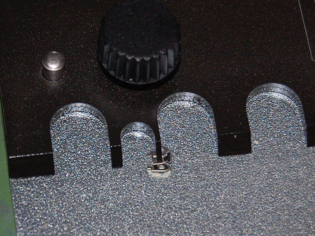
Another example of the detail Tameo is able to put in these WCT 1/43 kits.

Even the knobs you have to add yourself.
[imghttps://live.staticflickr.com/65535/50620888736_27c3ec0b6a_z.jpg][/img]
And drill a hole in it!!

On the tooth stick.
https://live.staticflickr.com/65535/506 ... 8249_z.jpg
And the prepared parts with the FE shift pattern.

Another template to bend the gear shift stick in the right form. I used mu nickel chromed after market rods as the original supplied steel ones are impossoble to bend with these short lengths.

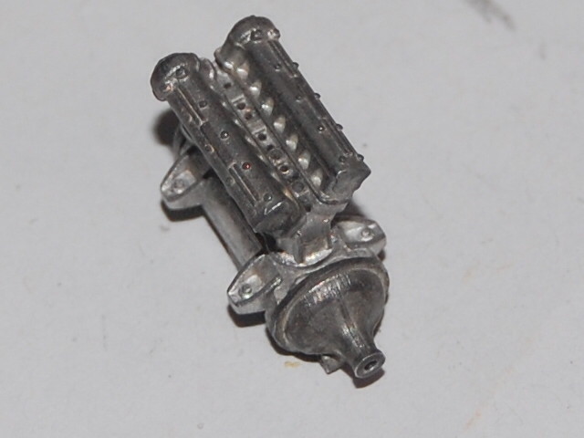
And the module to connect the shift module with the gear box.

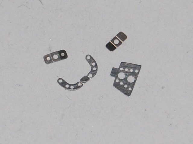
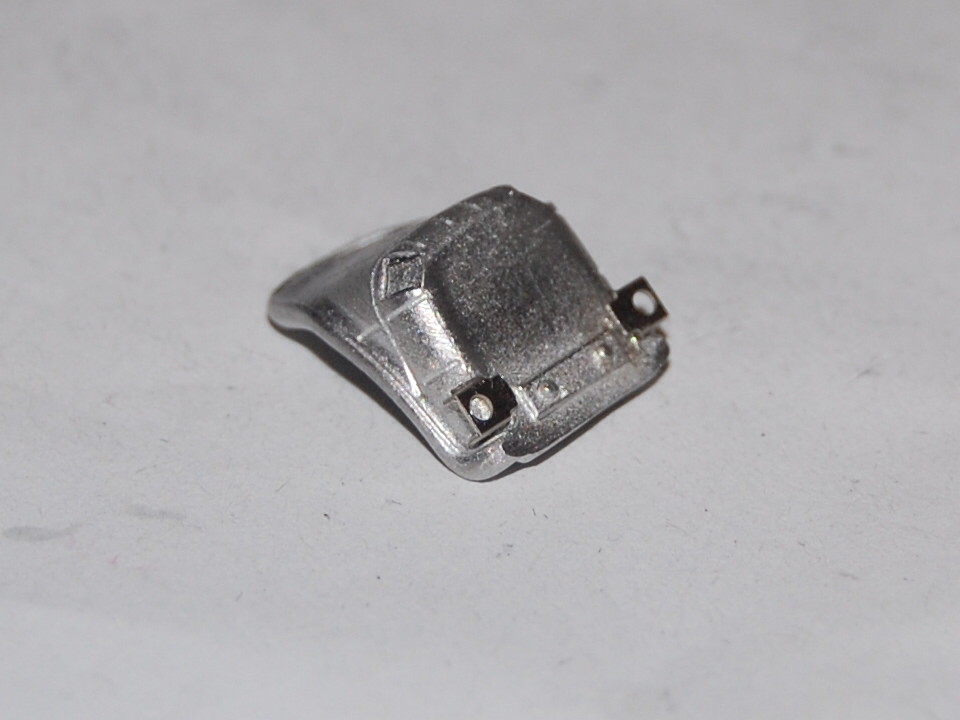
On with the dash. FE part with holes before bending an edge.

The dials find a home in the holes.


All 5 placed.

To place the tiny parts, I use a wax stick. Tweezers tend to shoot these parts away, never to be seen again,
The part sticks a bit on the pencil but loosenens easy when you glue the part.

The instrument decals on the dials.

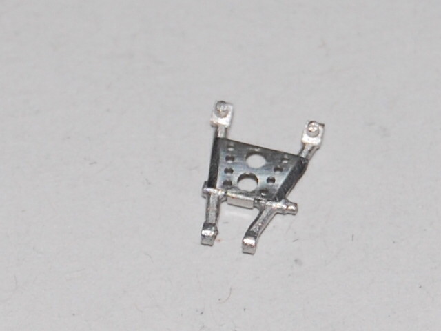
The dash has to be placed on the frame. A little FE switch also attached.
On the backside you have to add little brackets which origianally kept the instruments in place.

This way.

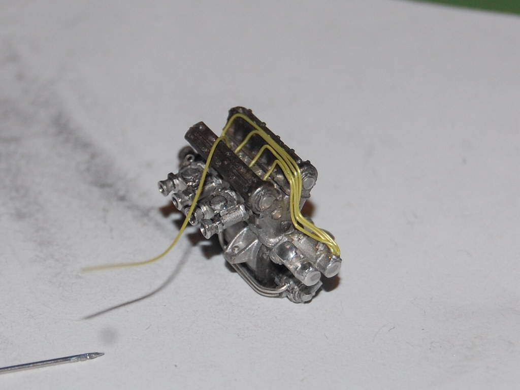
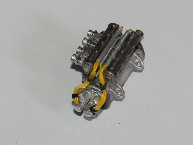
Added some wires. A little mod. Still long to have enough length to get them in the right place later.

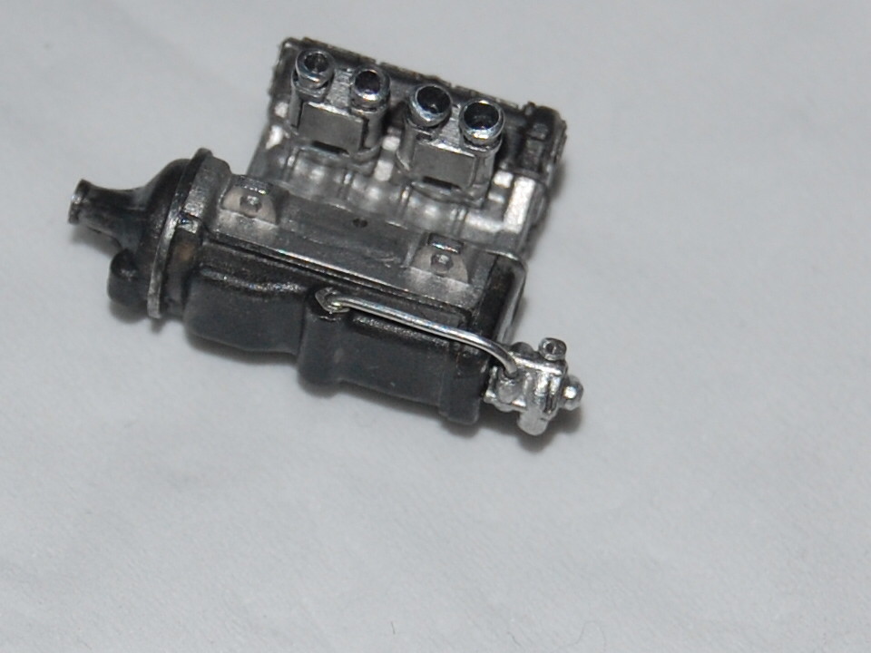
And on with the gear shift block. Polished and with a cover in the chassis colour.

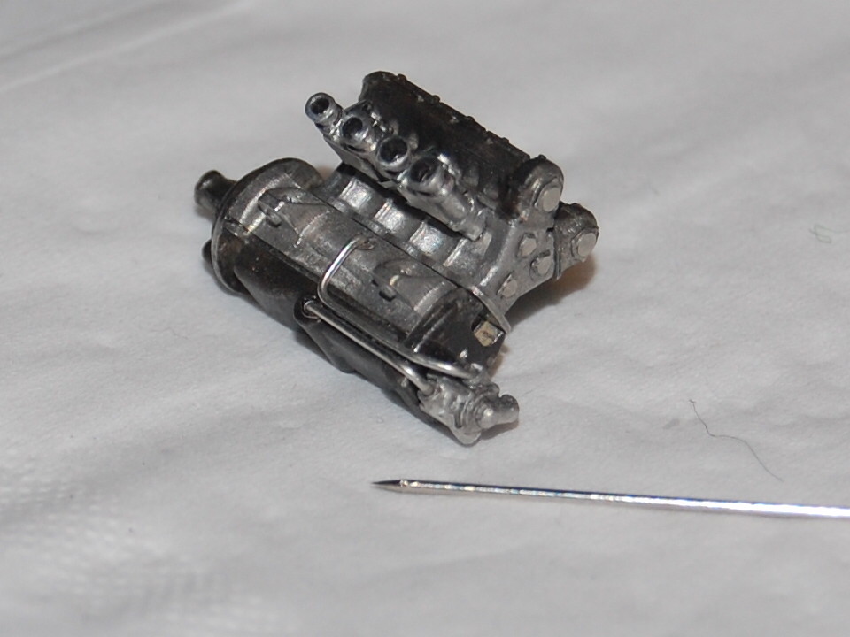
Assembled with al the pre worked parts.

On its final place.


Enough for today. Until next update.


